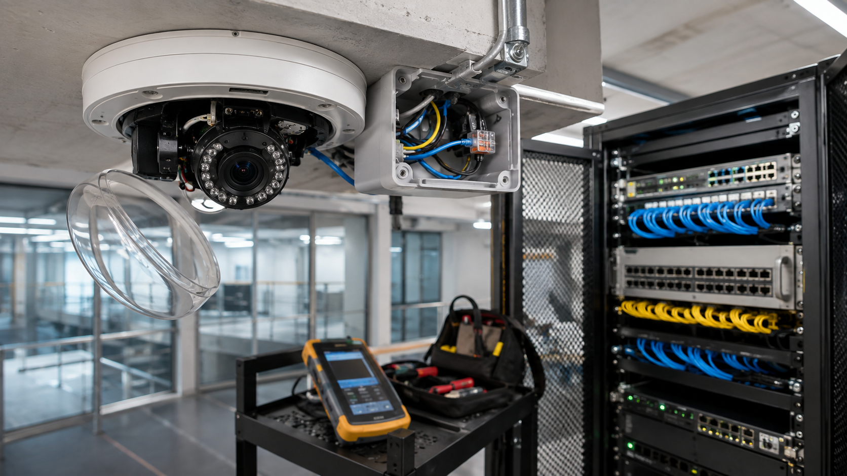
Security camera power issue repair is usually a fault-isolation job, not a camera-swap job. In a commercial CCTV system, the visible symptom—an offline camera, repeated reboot, missing infrared illumination, or a group of cameras dropping together—can originate at the facility power source, UPS, PoE switch or injector, cable plant, termination, local power supply, or the camera itself.
The fastest reliable approach is to prove the power path in order. Identify whether one camera, one switch group, or the entire system is affected. Then verify upstream power, PoE port state or local supply, cabling and terminations, and finally the camera on a known-good path. Recovery on a known-good port and cable argues against immediate camera replacement; continued failure on a proven compatible source makes the endpoint more suspect.
For broader problems involving recording, remote access, network identity, or storage, see Starlight Cabling’s commercial CCTV troubleshooting framework. This article deliberately narrows the diagnostic lens to power delivery and the physical dependencies that make a powered camera work.
Where camera power can fail before it reaches the endpoint
Typical IP/PoE architecture. Actual topology varies by site, manufacturer, recorder design, and whether cameras use PoE or separate local power.
A live switch does not prove usable power reaches the camera. The fault can sit at the power source, PoE allocation, cable path, termination, or endpoint; group failures often point to a shared upstream dependency.
Start with failure scope before touching hardware
Group the symptom by dependency. If one camera is dead while neighbors on the same switch remain stable, start with that port, patching, cable run, termination, and endpoint. If several cameras on one PoE switch disappear together, test the shared switch supply, UPS, available PoE budget, and switch state before visiting every camera. If all surveillance equipment drops together, the problem may sit farther upstream.
This is one reason commercial camera service should be treated as infrastructure work. Starlight Cabling’s current Security Camera service page and Structured Cabling service page show the overlap between CCTV endpoints and the physical network that supports them.
A dependency-first repair sequence
The objective is to isolate one failing domain with evidence before configuration changes or replacement parts create new variables.
Classify scope
One camera, one PoE group, one building area, or the whole system?
Verify upstream power
Confirm the switch, recorder, injector, UPS, or local supply is actually powered and stable.
Read PoE state
Check whether the PSE detects the device, grants power, reports denial, overload, or budget pressure.
Prove the cable path
Inspect patching and terminations; test wire map and power delivery with appropriate test equipment.
Substitute known-good elements
Use a compatible known-good port, short cable, injector, or camera to separate infrastructure from endpoint.
Repair the confirmed domain
Correct the source, port, cabling, termination, power class, or endpoint only after the evidence converges.
The useful outcome is not merely “the camera came back.” A maintainable repair identifies which dependency failed and why the corrective action belongs there.
PoE power problems are negotiation and budget problems as well as wiring problems
IEEE-standard Power over Ethernet separates the power-sourcing equipment (PSE)—for example a PoE switch—from the powered device (PD), such as an IP camera. The PSE detects a compatible device and allocates power before normal operation. Cisco’s current Catalyst troubleshooting documentation explicitly warns that PoE capability alone does not guarantee that power will be assigned to a connected device. Available switch power, port state, classification, and platform-specific restrictions can all matter.
The IEEE 802.3 PoE family includes Type 1 through Type 4. Fluke Networks summarizes maximum sourced levels of 15.4 W, 30 W, 60 W, and 90 W respectively, with less available at the powered device because of link losses. These are standard limits, not camera requirements. The camera datasheet and PSE capabilities remain the controlling compatibility references.
Power class is a compatibility ceiling, not a diagnosis
Use these IEEE type limits to understand the system architecture, then verify the installed camera’s actual requirement and the switch’s available budget.
Up to 15.4 W sourced by the PSE. Lower power is available to the powered device.
Up to 30 W sourced. Commonly called PoE+ in manufacturer documentation.
Up to 60 W sourced using four-pair PoE capability.
Up to 90 W sourced. High-power capability does not remove the need to verify the device requirement.
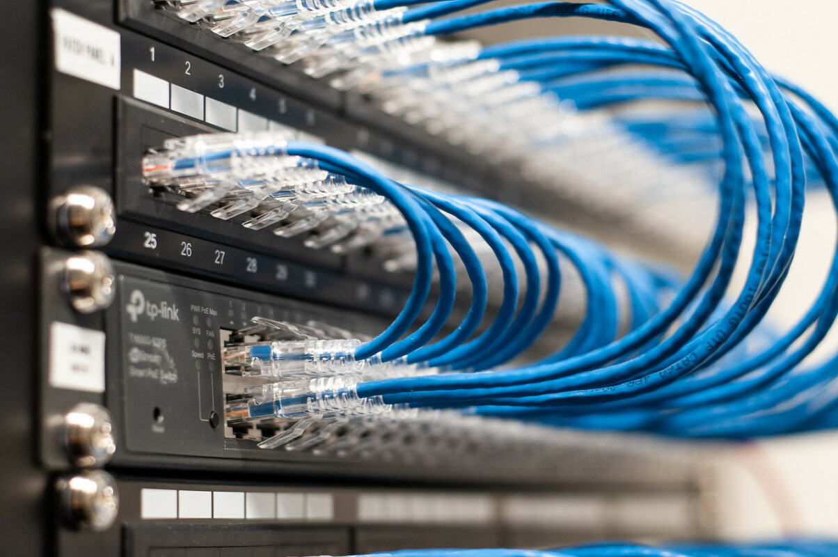
A port can be electrically capable of PoE and still deny or limit a camera because of allocation, classification, total switch budget, cabling, or device compatibility. Diagnose the installed path rather than relying on the word “PoE” on the label.
Cabling can carry data poorly, power poorly, or fail only under load
A visual inspection of an RJ45 plug is not enough to clear the cable plant. PoE depends on the copper conductors and terminations as an electrical path. Opens, shorts, miswires, damaged pairs, poor terminations, excessive resistance, and resistance imbalance can all create faults or instability. Fluke Networks’ PoE guidance emphasizes testing the cabling and, when appropriate, testing power under load rather than assuming a passing link light proves the cable is healthy for the intended PoE device.
Intermittent faults need special attention. A camera may boot in daylight and reboot when a heater, infrared illumination, motor, or other feature raises demand; another may fail after a marginal connector warms or the switch’s total PoE budget changes. Axis documents device cases where insufficient PoE class can limit full functionality. That is not proof of a power shortage, but it is a reason to correlate dropouts with power events before resetting the device.
What the visible symptom suggests—and what it does not prove
These are fault domains to test, not probability rankings. Site topology and manufacturer behavior can change the correct order.
- Plausible domain
- Port, patching, horizontal cable, termination, power negotiation, camera.
- Verification
- Compare with a known-good port and short compatible cable; review PSE state and cable test results.
- Practical consequence
- Do not replace the camera until the original path is isolated.
- Plausible domain
- Switch power supply, UPS, total PoE budget, configuration, or switch fault.
- Verification
- Compare affected ports, logs, power allocation, upstream supply, and a known-good powered device.
- Practical consequence
- Prioritize the shared dependency before separate endpoint repairs.
- Plausible domain
- Marginal PoE delivery, termination, cable resistance, thermal condition, or endpoint fault.
- Verification
- Correlate timestamps with port events, load tests, environmental changes, and device logs.
- Practical consequence
- A reboot may temporarily hide the fault without removing it.
- Plausible domain
- Original permanent link, patching, connector, intermediate device, or switch port.
- Verification
- Move one known-good element at a time back into the original path.
- Practical consequence
- The endpoint has demonstrated that it can operate on at least one compatible source.
- Plausible domain
- Insufficient available power, negotiation issue, device mode, or endpoint electronics.
- Verification
- Compare required power with negotiated/allocated power and repeat under the operating condition that triggers failure.
- Practical consequence
- “Online” is not the same as proven stable under maximum intended load.
- Plausible domain
- Cable fault, incompatible intermediary, damaged connector, or failed powered-device interface.
- Verification
- Test a short direct cable and a compatible known-good camera on the same port.
- Practical consequence
- The comparison separates PSE behavior from the suspect endpoint and field link.
Symptom-based troubleshooting becomes useful only when each symptom is tied to a measurable failure domain and a comparison that can falsify the first assumption.
Known-good substitution is powerful only when the test stays controlled
Controlled substitution is one of the strongest CCTV power tests: change one element while everything else stays constant. Move the suspect camera to a proven compatible port with a short known-good cable. Put a known-good camera on the suspect field run. Move the field run to another verified port. If an injector or midspan exists, substitute it only when device requirements and the installation design permit.
Changing several variables at once can make a fault disappear without identifying it. Rebooting the switch, replacing the patch lead, moving the port, and resetting the camera may restore video but destroys diagnostic information. That makes repeat failures harder to explain.
Four comparisons that separate endpoint from infrastructure
Each comparison changes one dependency and preserves the rest of the test as far as practical.
A — Suspect camera + known-good port/cable
If it works: investigate the original port, patching, permanent link, or intermediary device. If it fails: endpoint compatibility, configuration, or hardware becomes more likely.
B — Known-good camera + suspect field run
If it fails similarly: the field path gains suspicion. If it works: compare the original camera’s power requirement and condition.
C — Same field run + different verified port
If it recovers: review the original PSE port, configuration, allocation, or hardware. If not: continue toward the field link or endpoint.
D — Same camera under triggering load
Repeat the test when infrared, heater, PTZ motion, or another relevant function is active if that operating state is associated with the failure.
A known-good test is evidence only when “known-good” also means electrically compatible with the device under test. The goal is controlled comparison, not random swapping.
Separate PoE failures from locally powered and analog camera failures
Not every commercial camera receives power through Ethernet. Some IP cameras use separate DC or AC inputs; analog systems commonly have a video path over coax or another transport plus a separate local or centralized power path. In those systems, “no video” and “no power” are different questions. A camera can have power but lose video transport, or the recorder can lose an input while the camera remains energized.
For separate-power systems, confirm the rated supply method from the equipment documentation before substituting adapters or distribution outputs. Voltage, polarity, current capacity, connector type, grounding, and environmental installation requirements are product-specific. An adapter that physically fits is not proof of compatibility. Centralized power-distribution faults can also create group symptoms that resemble a recorder failure.
PoE combines power and data; separate-power systems do not
Different architectures require different isolation logic.
Switch / injector / recorder PoE port
Same copper link carries data and DC power
Negotiates and operates as powered device
Stream continues to NVR/VMS
Local adapter or centralized distribution
Receives dedicated power path
Separate transport such as coax
Receives video independently of camera power source
The same “black screen” symptom can sit in different physical paths. Identify the installed topology before deciding which measurement or substitution has diagnostic value.
Repair the confirmed fault domain, then verify the system under normal load
A repair may be as small as reterminating a damaged link or replacing a failed patch lead, or as broad as correcting an overloaded PoE design. The boundary is evidence. If the camera works on a compatible known-good path but not the installed run, replacing it does not repair the infrastructure. If multiple ports show power denial because switch budget is insufficient, moving cameras may only move the symptom.
After correction, verify more than a live image. Confirm stable power and link state, expected camera functions, recording, time synchronization, and the condition that previously triggered failure. For intermittent faults, preserve timestamps and compare them with switch, UPS, and device events. Document what changed.
Repair infrastructure when the camera passes on a proven compatible path. Replace or manufacturer-service the endpoint when the power source, port, cabling, negotiation, and compatibility have been proven and the camera still cannot operate reliably. Replace a power component when testing confirms that component—not merely a downstream symptom—is the failed dependency.
Electrical safety sets a hard boundary for field troubleshooting
PoE diagnostics at network equipment are not permission to work inside energized AC equipment. OSHA’s general-industry electrical work-practice rule requires qualified persons for work on energized circuit parts and for testing where employees may be exposed to energized parts. Keep low-voltage fault isolation separate from branch circuits, UPS internals, distribution equipment, or other exposed energized components unless the person is qualified and applicable safety procedures are followed.
For business owners and IT managers, the practical rule is simple: gather symptoms, port states, logs, cable-test results, and equipment models; do not convert a CCTV troubleshooting exercise into unauthorized energized electrical work.
Need a commercial camera power fault isolated?
If your Orange County business has offline cameras, repeated PoE reboots, a suspect cable path, or several cameras failing on a shared switch, provide the affected locations, equipment models, symptom pattern, and any recent outage or network change when requesting service.
Related Starlight Cabling Guides
Sources and Verification
- IEEE 802.3-2022 — Ethernet standard. Used to verify the current standards family context for Ethernet and Power over Ethernet.
- Cisco — Troubleshoot Power over Ethernet on Catalyst 9000 Switches. Supports the distinction between PSE, PD, power assignment, port state, and switch power-budget diagnostics.
- Fluke Networks — 4-Pair PoE Standards & Cabling Guide. Supports the IEEE PoE type limits and the relationship between power delivery and the cabling plant.
- Fluke Networks — What Is PoE Negotiation and How Does It Work?. Supports discovery, classification, and operation as distinct PoE stages.
- Axis Communications — Power settings. Manufacturer example showing that device functionality can be affected when available PoE class is below the level expected for full operation.
- OSHA — 29 CFR 1910.333. Supports the safety boundary around work and testing involving exposed energized electrical parts.
Before you replace the camera
The decision can be reduced to one question: has the camera been tested on a power source and physical path that are known to meet its requirements? If not, replacement is premature. Prove the upstream source, PoE assignment or local supply, cable path, termination, and a compatible known-good comparison first. Then repeat the test under the operating condition that produced the failure.
For commercial security camera power issue repair, that discipline matters more than a quick reboot. It prevents a failed patch lead from becoming an unnecessary camera purchase, prevents an overloaded PoE switch from being mistaken for multiple bad cameras, and turns intermittent outages into documented infrastructure faults that can actually be corrected.
Technical note: PoE type limits describe standards capability. Exact camera power requirements, supported power methods, switch behavior, cable requirements, and repair procedures remain product- and site-specific; verify current manufacturer documentation for the installed equipment.